

I. Introduction to the Training Device
The intelligent production line training device is a modular teaching workstation for automatic assembly. It covers the application of various technologies such as interconnection control technology, transmission technology, human-machine interaction (HMI) technology, visual inspection technology, mechanical technology, sensing and pneumatic technology, and multiple industrial fieldbus communication technologies. Among them, the carriers of interconnection control and human-machine interaction (HMI) technology are equipped with first-line brands at home and abroad as standard, which ensures the stability and reliability of the intelligent training device in the process of system teaching.
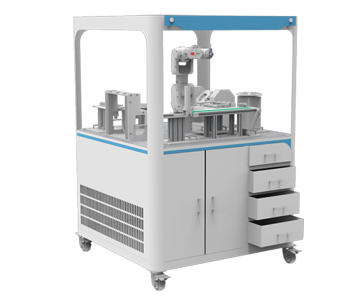
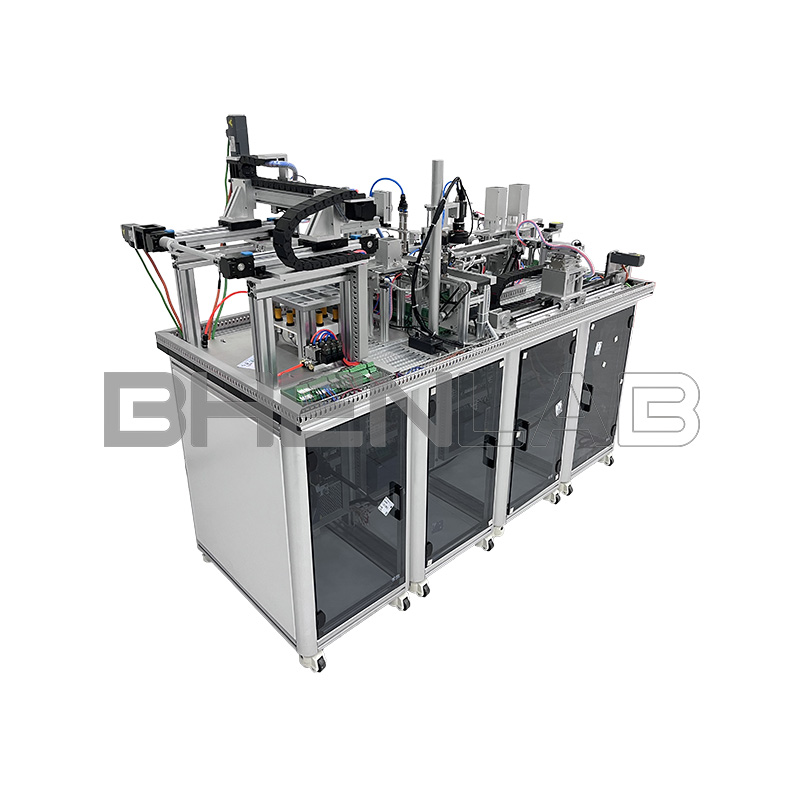
Figure 1 Front Model Diagram of the Assembled Equipment of the Intelligent Production Line Training Device
The intelligent production line training device is composed of four workstations: feeding workstation, assembly workstation, inspection workstation, and storage workstation. It includes working units such as a feeding unit, manipulator handling unit, assembly unit, conveying unit (horizontal/vertical), visual inspection unit, information writing/reading unit, gantry mechanism storage unit, human-machine interaction unit, and multi-station collaborative control unit. Moreover, this training device can be used for comprehensive training in group cooperation, and also for single-station training by individuals or with one unit.
The intelligent production line training device is composed of four workstations: feeding workstation, assembly workstation, inspection workstation, and storage workstation. It includes working units such as a feeding unit, manipulator handling unit, assembly unit, conveying unit (horizontal/vertical), visual inspection unit, information writing/reading unit, gantry mechanism storage unit, human-machine interaction unit, and multi-station collaborative control unit. Moreover, this training device can be used for comprehensive training in group cooperation, and also for single-station training by individuals or with one unit.
In some areas with narrow passages, the separated design can greatly facilitate handling and transportation. At the same time, the separated modular design facilitates the update and iteration of subsequent equipment of the intelligent production line training device, and when some module equipment of the intelligent production line training device is damaged, it can be repaired by simply replacing the corresponding equipment module.
Station 3
Station 4 Inspection Workstation
Station 2
Assembly Workstation
Storage Workstation
Station 1
Feeding Workstation
Figure 2 Distribution Diagram of Workstations of the Intelligent Production Line Training Device
Station 4 Inspection Workstation
Station 2
Assembly Workstation
Storage Workstation
Station 1
Feeding Workstation
Figure 2 Distribution Diagram of Workstations of the Intelligent Production Line Training Device
Technical Parameters:
- Input power supply: single-phase three-wire ~220V±10% 50Hz
- Temperature: -5℃~+40℃, relative humidity <85% (25℃)
- Equipment power: <2.0 kw
- Overall dimensions: length × width × height: 1600mm×600mm×1300mm
The intelligent production line training device is mainly divided into four workstations: feeding workstation, assembly workstation, inspection workstation, and storage workstation. The feeding workstation mainly realizes the pushing out of material bottles, information writing (RFID), and transportation; the assembly workstation is mainly responsible for assembling materials that meet the order to the bottle body according to the barcode order information; the inspection workstation uses visual inspection technology to detect defects of the assembled products, compares them with the order information, and covers them if there is no error, otherwise, it performs rejection operation; the storage workstation transports the assembled and covered materials to the warehouse by identifying the information (RFID) on the material bottles and combining with the storage location sensor using the gantry mechanism.
The intelligent production line training device simulates the application of particle filling production lines. Log in to the permission account on the human-machine interaction unit, confirm the key parameters of the production line. After the parameters are confirmed to be correct, press the start button to start the equipment. The well-type feeding module cylinder of the feeding workstation pushes the material bottle out of the silo. The manipulator handling unit clamps the material, writes information (RFID), and then transports the material bottle to the conveying unit of the assembly workstation. The conveying unit first conveys the material bottle to the order identification unit for order information identification, and then loads the corresponding type and quantity of materials according to the order information identified by scanning the code. After the assembly is completed, the manipulator handling unit transfers the materials on the assembly workstation to the conveying unit of the inspection workstation for visual inspection of the assembled materials. If the inspection is correct, the material bottle is covered (if the inspection finds defects or does not meet the order information, rejection processing is performed). After the covering is completed, it is pushed out to the position to be grabbed for storage. By identifying the information (RFID) on the material bottle and combining with the storage location sensor, finally, the gantry mechanism storage unit clamps the qualified products and stores them in the warehouse.
II. Introduction to Workstations
- Feeding Workstation
Figure 3 Feeding Workstation
The feeding workstation is mainly composed of a bottle feeding unit, a bottle information reading and writing unit, and a sliding table manipulator. As shown in Figure 3 below, it is the bottle feeding unit of the feeding workstation.
(1) Bottle Feeding Unit
The feeding workstation is mainly composed of a bottle feeding unit, a bottle information reading and writing unit, and a sliding table manipulator. As shown in Figure 3 below, it is the bottle feeding unit of the feeding workstation.
(1) Bottle Feeding Unit
Figure 4 Bottle Feeding Unit
The bottle feeding unit adopts a double well-type feeding structure, with two silos, which can store two types of material bottles at the same time as a double-position discharging mechanism. When the device is started, the pushing cylinders on the left and right sides push the materials out of the silo (only one side is pushed out at the same time). After being pushed to the discharging platform, the platform discharging cylinder pushes the materials out to the clamping position.
The bottle feeding unit adopts a double well-type feeding structure, with two silos, which can store two types of material bottles at the same time as a double-position discharging mechanism. When the device is started, the pushing cylinders on the left and right sides push the materials out of the silo (only one side is pushed out at the same time). After being pushed to the discharging platform, the platform discharging cylinder pushes the materials out to the clamping position.
(2) Manipulator Handling Unit
Figure 5 Manipulator Handling Unit
The manipulator handling unit is driven and controlled by a servo motor, which can achieve precise positioning within the stroke. At the same time, it uses a variety of cylinders (lifting cylinder, rotating cylinder, biaxial cylinder, pneumatic finger) to cooperate with actions to realize the grabbing and placing of materials.
The manipulator handling unit is driven and controlled by a servo motor, which can achieve precise positioning within the stroke. At the same time, it uses a variety of cylinders (lifting cylinder, rotating cylinder, biaxial cylinder, pneumatic finger) to cooperate with actions to realize the grabbing and placing of materials.
(3) Information Writing Unit
Figure 6 Information Writing Unit
The information writing unit adopts RFID reading and writing technology, and uses a high-frequency reader to write information into the electronic tags preset on the material bottles, which facilitates subsequent classified storage, information entry and other operations.
The information writing unit adopts RFID reading and writing technology, and uses a high-frequency reader to write information into the electronic tags preset on the material bottles, which facilitates subsequent classified storage, information entry and other operations.
- Assembly Workstation
Figure 7 Assembly Workstation
The assembly workstation is mainly composed of an assembly material feeding unit, an assembly unit, an order information identification module, and a horizontal conveying unit.
The assembly workstation is mainly composed of an assembly material feeding unit, an assembly unit, an order information identification module, and a horizontal conveying unit.
(1) Assembly Material Feeding Unit
As shown in Figure 5, it is the assembly material feeding unit of the assembly workstation.
As shown in Figure 5, it is the assembly material feeding unit of the assembly workstation.
Figure 8 Assembly Material Feeding Unit
Similar to the bottle feeding unit of the feeding station, the assembly material feeding unit is designed with a double well-type feeding structure, which can provide materials of different specifications for assembly according to the identification results of the order information identification module.
Similar to the bottle feeding unit of the feeding station, the assembly material feeding unit is designed with a double well-type feeding structure, which can provide materials of different specifications for assembly according to the identification results of the order information identification module.
(2) Assembly Unit
Figure 9 Assembly Unit
After the materials that meet the order information are pushed out of the silo, the assembly unit uses pneumatic suction to suck the materials to be assembled from the material platform and place them into the bottles to be assembled on the horizontal conveyor belt. As shown in Figure 6, it is the model of the assembly unit.
After the materials that meet the order information are pushed out of the silo, the assembly unit uses pneumatic suction to suck the materials to be assembled from the material platform and place them into the bottles to be assembled on the horizontal conveyor belt. As shown in Figure 6, it is the model of the assembly unit.
Figure 10 Horizontal Conveying Unit
(3) Horizontal Conveying Unit
As shown in Figure 7, it is the horizontal conveying unit of the assembly workstation. When the bottle materials from the feeding workstation are placed on the horizontal conveying unit by the manipulator handling unit, the photoelectric switch at the head end is triggered, the order information identification module (code scanner) scans the barcode to obtain the order information. After the identification is completed, the conveyor belt runs and transmits to the end assembly position, the end sensor is triggered, the conveyor belt stops running, and the assembly unit sucks the materials to be assembled from the platform and places them into the bottles to be assembled to complete the assembly.
- Inspection Workstation
Figure 11 Inspection Workstation
The inspection workstation includes a visual inspection unit, a capping assembly unit, a vertical conveying unit, etc. After the completion of the assembly workstation, the manipulator handling unit transfers the materials from the horizontal conveying unit to the vertical conveying unit. After passing through the visual inspection mechanism, it is decided whether the materials are capped, transported to the warehouse, or rejected and recycled.
(1) Visual Inspection Unit
As shown in Figure 8, it is a schematic diagram of the visual inspection unit model. The visual inspection unit can perform defect detection or size and shape detection through specific algorithms, usually used as defect detection, and detect whether the object meets the requirements through image comparison.
As shown in Figure 8, it is a schematic diagram of the visual inspection unit model. The visual inspection unit can perform defect detection or size and shape detection through specific algorithms, usually used as defect detection, and detect whether the object meets the requirements through image comparison.
Figure 12 Visual Inspection Unit
(2) Capping Assembly Unit
Figure 13 Capping Assembly Unit
As shown in Figure 9, it is the capping assembly unit. When the front visual inspection determines that the assembly needs to be stored in the warehouse, the capping assembly unit performs capping assembly operation, otherwise, the assembly is directly sent to the end by the vertical conveying unit for rejection and recycling.
Figure 14 Vertical Conveying Unit
(3) Vertical Conveying Unit
The vertical conveying unit is driven by a three-phase AC motor and uses a cylinder as the executive mechanism. It is used for pneumatic material blocking, material storage, material clamping, and material recycling. It is equipped with a rejection storage position and a to-be-stored track, and an information reading module is installed under the track. As shown in Figure 10, it is a schematic diagram of the vertical conveying unit model.
Figure 15 Storage Workstation
4. Storage Workstation
The storage workstation mainly consists of a gantry manipulator module, an information reading module (RFID), and a storage location platform module. Before the storage workstation runs, the materials from the inspection workstation need to slide onto the storage track. After the information reading module reads and identifies the content, the corresponding storage location is allocated according to the read information. The gantry manipulator module grabs the assembled products and transports them to the corresponding storage location.
(1) Gantry Manipulator Module
Figure 16 Gantry Manipulator
The XY axis of the gantry manipulator module is driven by a servo motor to achieve precise positioning of product placement, and the Z axis and product grabbing/placement adopt a pneumatic structure to improve the efficiency of fixed-point grabbing and placing.
Figure 16 Gantry Manipulator
The XY axis of the gantry manipulator module is driven by a servo motor to achieve precise positioning of product placement, and the Z axis and product grabbing/placement adopt a pneumatic structure to improve the efficiency of fixed-point grabbing and placing.
(2) Storage Location Platform Module
Figure 17 Storage Location Platform Module
The storage location platform module adopts a 3×3 storage location layout, and each storage location is equipped with a storage location sensor to monitor the usage of storage locations and avoid collisions caused by repeated storage locations.
The storage location platform module adopts a 3×3 storage location layout, and each storage location is equipped with a storage location sensor to monitor the usage of storage locations and avoid collisions caused by repeated storage locations.
(3) Human-Machine Interaction Unit
Figure 18 Human-Machine Interaction Unit
The human-machine interaction unit is equipped with an industrial touch screen, which can perform human-machine interface configuration of production line equipment. In the configuration interface, it can realize automatic control of the comprehensive and single-station production line, monitor the working/production status and parameters of production line equipment, adjust key parameters in the production process, and alarm equipment failures.
To ensure the safety of the production process, the factory-set touch screen program has multi-level permissions. Ordinary users can only view the production data dashboard and perform start-stop operations. Modifying production parameters requires logging in to the permission user account through identity authentication, and then can modify the key production parameters.
III. Overall Display of Workstations
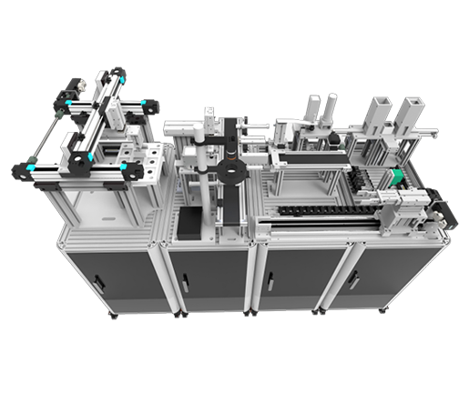
Figure 19 Side View of Feeding Workstation and Assembly Workstation
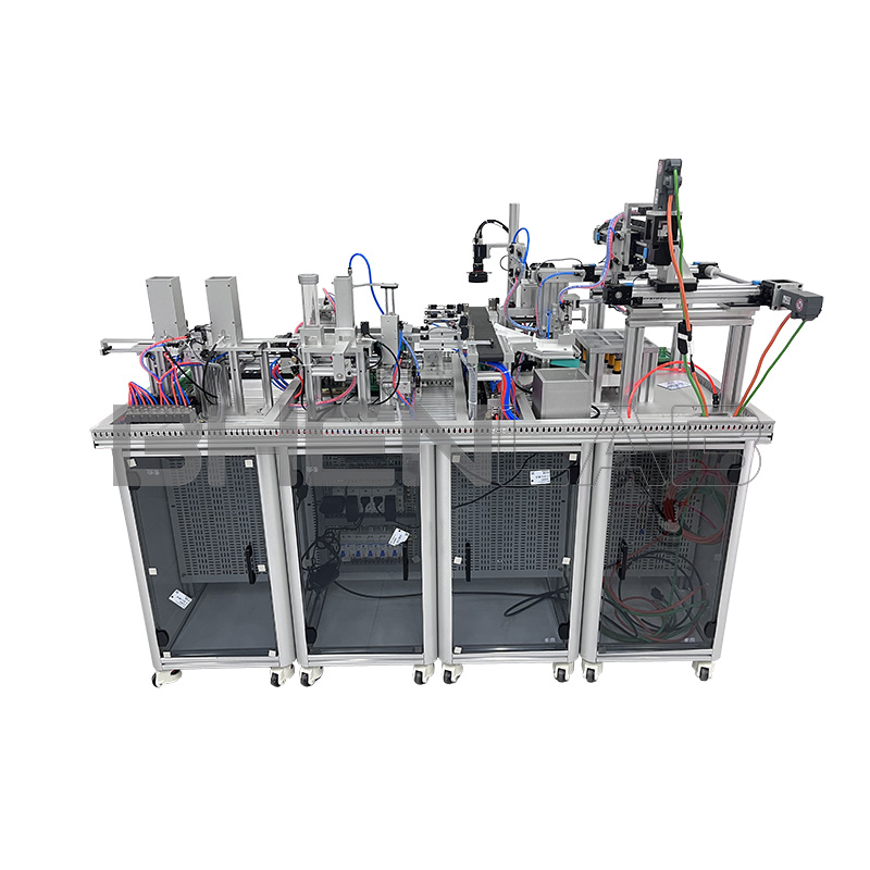
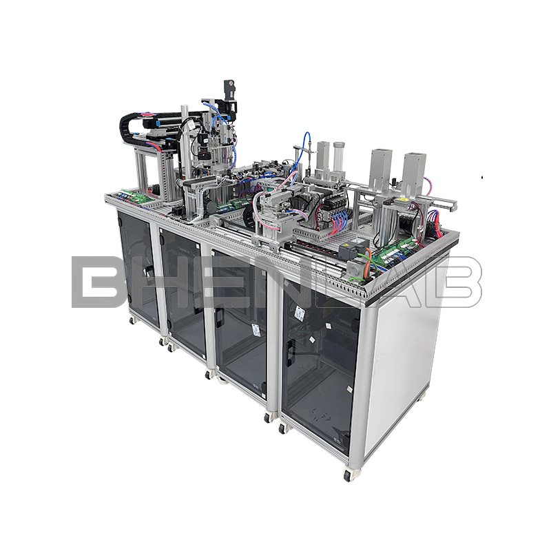
Figure 20 Side View of Workstations
Figure 20 Side View of Workstations
IV. Detailed Equipment Parameters of Workstations
| Unit | Component | Model/Specification | Quantity | Remarks |
|---|---|---|---|---|
| Biaxial cylinder | TN10 X 100 | 1 | ||
| Fiber optic sensor | 24V, NPN | 2 | Cylindrical, M3, with amplifier | |
| Feeding Workstation | RFID (Information Writing Unit) | THS430-RJ45 TCP/IP | 1 | High frequency, TCP/IP network protocol |
| RFID tag card | H2XD13K | 10 | High frequency RFID, anti-metal, ISO15693 | |
| Thin cylinder | CQ2B50-30D | 1 | ||
| Swing cylinder | MSQB10L2 | 1 | ||
| Biaxial cylinder | TN16 X 50 | 1 | ||
| Pneumatic finger | HFZ20(CL) | 1 | ||
| Drag chain | ||||
| Servo driver | 6SL3210-5FB10-2UA2 | 1 | V90 servo | |
| Servo motor | 1FL6042-2AF21-1AA1 | 1 | Servo matching motor | |
| Slot-type photoelectric switch | EE-SX674A-WR | 3 | (NPN) output, limit | |
| Solenoid valve | 4v210 | 1 | 8-position valve group (inlet φ6, outlet φ4) | |
| Biaxial cylinder | TN16 X 75 | 1 | ||
| Pen-shaped cylinder | CJ2KB16-75 | 1 | Hexagon socket piston rod | |
| Vacuum 吸盘 | ZPT25BN-A6 | 1 | Long tooth type | |
| Vacuum generator | CV10-HS | 1 | Equipped with black joint muffler | |
| Biaxial cylinder | TN10 X 60 | 1 | ||
| Swing cylinder | MSQB10L2 | 1 | ||
| Photoelectric switch sensor | E3ZG-D61 2M | 3 | 24V, NPN | |
| Fiber optic sensor | 2 | Cylindrical, M3, with amplifier | ||
| Assembly Workstation | DC motor | ZGB37RG | 1 | Rotating speed 50r/min |
| Code scanner | CR-130M | 1 | ||
| Solenoid valve | 4v210 | 1 | 5-position valve group (inlet φ6, outlet φ4) | |
| Belt | 1 | Perimeter: 703mm, width: 60mm, PVC green/black | ||
| Pen-shaped cylinder | CJ2KB16-20 | 1 | Hexagon socket piston rod | |
| Biaxial cylinder | TN10 X 60 | 2 | ||
| Photoelectric switch sensor | E3ZG-D61 2M | 7 | 24V, NPN | |
| Three-phase AC motor | 4IK25GN-S3 | 1 | ||
| Belt | 1 | Perimeter: 1263mm, width: 60mm, PVC green/black | ||
| Synchronous wheel | 3M30 teeth, φ10 | 2 | Flat on both sides | |
| Synchronous belt | 1 | Perimeter: 501mm, width: 11mm, PVC black | ||
| Unpowered roller | φ5mm cylinder, PVC | |||
| Inspection Workstation | RFID | THS630-RJ45 TCP/IP | 1 | Ordinary model |
| Pen-shaped cylinder | CJ2KB16-75 | 1 | Hexagon socket piston rod | |
| Biaxial cylinder | TN16 X 90 | 1 | ||
| Biaxial cylinder | TN16 X 30 | 1 | ||
| Fiber optic sensor (cylindrical) | 3M large | 1 | ||
| Vacuum 吸盘 | ZPT13UNK10-B5-A10 | 2 | Stroke can rotate 10MM | |
| Vacuum generator | CV10-HS | 1 | Equipped with black joint muffler | |
| Solenoid valve | 4v210 | 1 | 9-position valve group (inlet φ6, outlet φ4) | |
| Camera | MV-CE050-30UC | 1 | Including cable | |
| Lens | MVL-HF1224M-10MP | 1 | ||
| Light source | MV-LRDS-90-90-W | 1 | Including light source cable: MV-LW-003-1-S | |
| Controller | MV-VB2210-120G | Not included (optional) | ||
| Software key | IMVS-VM-7200 | Not included (optional) | ||
| Linear module | Effective stroke 300, YH-TBD40 | 2 | With fixed seat | |
| Linear module | Effective stroke 450, YH-TBD40 | 1 | With fixed seat | |
| Biaxial cylinder | TN16 X 40 | 1 | ||
| Biaxial cylinder | TN16 X 75 | 1 | ||
| Pneumatic finger | HFZ20(CL) | 1 | ||
| Slot-type photoelectric switch | EE-SX674A-WR | 6 | (NPN) output | |
| Storage Workstation (Gantry Manipulator Module) | Solenoid valve | 4v210 | 1 | 3-position valve group (inlet φ6, outlet φ4) |
| Servo controller | V90 servo, 6SL3210-5FB10-2UA2 | 2 | ||
| Servo motor | 1FL6042-2AF21-1AA1 | 2 | ||
| Coupling | φ10mm to φ10mm | 3 | ||
| Synchronous rod | φ10, length: 280mm | |||
| Photoelectric sensor | E3F-DS10P1 | 9 | (NPN) output | |
| Touch screen bracket | F150 | 1 | With handle + 4 buttons of 22mm | |
| Touch screen | Kunlun Tongtai | 1 | 7 inches | |
| Start button | Normally open and normally closed, green | 1 | Opening φ22 | |
| Reset button | Normally open and normally closed, yellow | 1 | Opening φ22 | |
| Stop button | Normally open and normally closed, red | 1 | Opening φ22 | |
| Emergency stop button | Normally closed | 1 | Opening φ22 | |
| Control Unit | PLC | 1214C DC/DC/DC Siemens 1200 | 4 | 6ES7214-1AG40-0XB0 |
| Expansion module | DI8*24VDC | 2 | 6ES7221-1BF32-0XB0 | |
| Expansion module | DI16*24VDC DQ16* |
BOH-XCF1Virtual-Real Integrated Intelligent Production Line Training Device
Tags: production line equipmentvirtual simulation production line equipmentCategories: Others, PLC training equipmentSKU: N/A
Brand: BHENLAB